

Robotic Multimodal CT inspection scanner for non-destructive testing (NDT).
RadalyX
Portable – Robotic – Multimodal
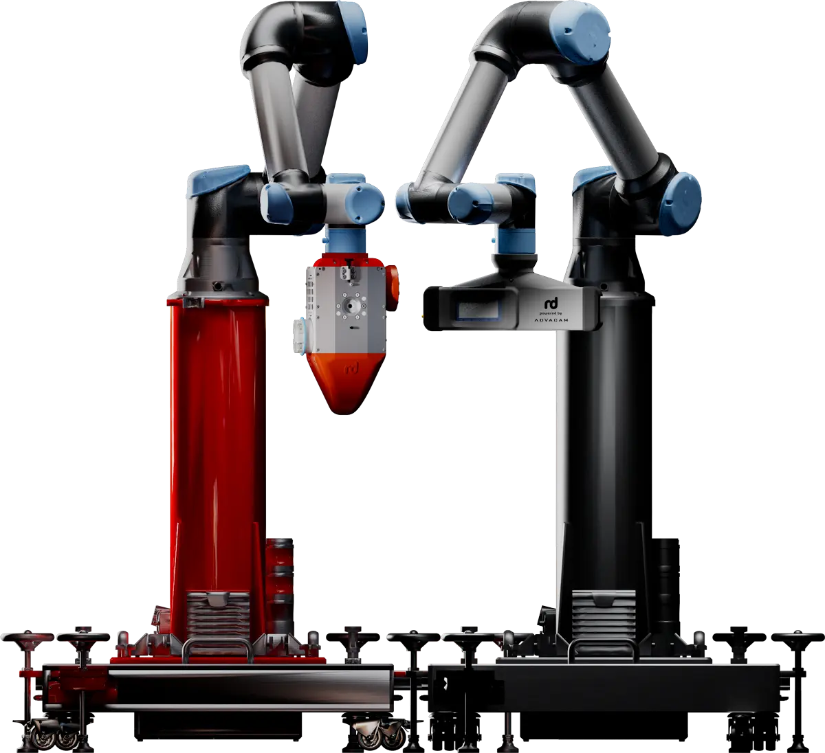
RadalyX is a portable and modular robotic X-ray imaging platform designed to bring the scanner to the object—not the object to the scanner.
Unlike conventional CT systems limited by the size of their inspection chamber, RadalyX performs high-quality inspections directly in production halls, maintenance facilities, laboratories or even aircraft hangars. Large, complex or fixed structures can now be inspected where they are located.
User-friendly automation
Built for simplicity, RadalyX dramatically simplifies advanced CT inspection. After just two days of training, virtually any operator can perform professional measurements with confidence.
Two synchronized six-axis robotic arms automatically position the X-ray source and detector, while intelligent software manages calibration, collision avoidance, scanning trajectories and data acquisition. Operators simply define the inspection task—the system takes care of the complexity.
RadalyX can also scan only the region of interest, significantly reducing acquisition time while maintaining the information that matters.
Engineered for your inspection challenge.
Portable yet sensitive
Portability should never compromise image quality. Powered by ADVACAM photon-counting detectors, RadalyX delivers exceptional image quality, high dynamic range and energy-resolved X-ray imaging in a truly mobile robotic platform.
Every X-ray photon matters. Photon-counting technology captures each one individually, revealing subtle material differences, low-contrast defects and fine structural details that conventional systems often miss. Its spectral capabilities further enable advanced material discrimination and elemental analysis, extending inspection far beyond conventional radiography.
One platform. Multiple inspection methods. From high-resolution 2D X-ray imaging and CT to ultrasound and advanced spectral analysis, RadalyX lets you select exactly the inspection method—or combination of methods—your application requires, without the complexity of multiple dedicated systems.
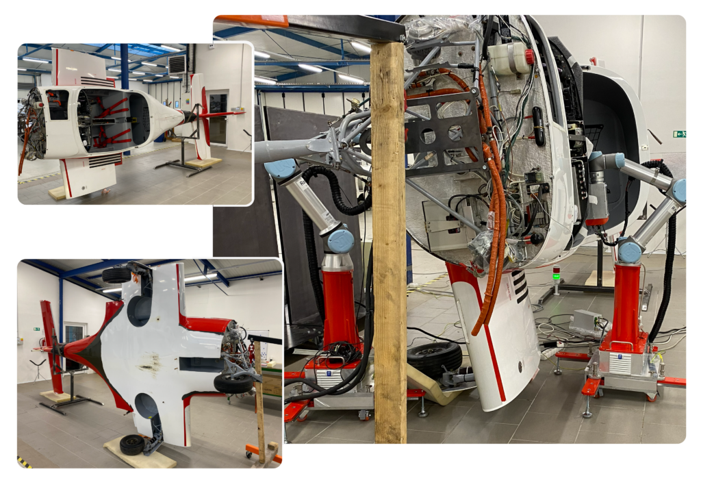
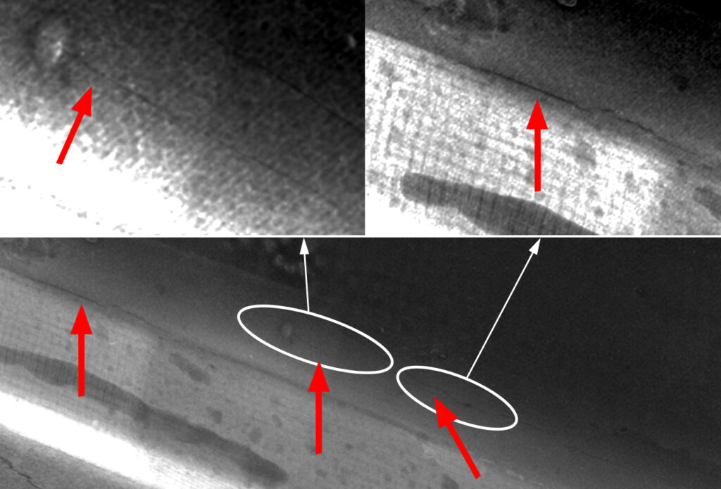
The capabilities of RadalyX are best proven in demanding inspection tasks. Following an aircraft incident in which the aircraft slid across grass with the landing gear retracted (Figure 1), RadalyX revealed cracks in the carbon-fibre fuselage structure, providing clear, high-resolution insight into damage that would be difficult to detect using conventional X-ray imaging.
NO DISMANTLING OR CUTTING
Inspection should adapt to the object—not the other way around. RadalyX brings laboratory-grade X-ray inspection directly on large or assembled components, enabling non-destructive evaluation of large, complex and difficult-to-access structures without dismantling or sectioning.
Instead of scanning the entire object, RadalyX can focus on the region of interest, reducing inspection time while preserving the information that matters. Adaptive robotic trajectories allow the system to inspect from virtually any angle, reaching locations inaccessible to conventional CT scanners.
Advanced robotic X-ray scanning enables precise, parallax-free 2D and 3D imaging of curved surfaces and complex structures. The robot automatically follows the object’s geometry, maintaining a constant distance and perpendicular alignment to the surface throughout the scan. This approach delivers accurate, distortion-free imaging, making it particularly valuable for non-destructive inspection of curved panels and honeycomb structures, including composite materials.
FOCUSED X-RAYS (IF NO CT IS POSSIBLE)
Sometimes a full CT scan is unnecessary. By combining robotic motion with advanced image reconstruction, RadalyX performs tomosynthesis imaging that focuses on selected depth planes and regions of interest within the inspected object. Instead of overlapping all internal structures into a single projection, individual layers become clearly distinguishable, making hidden defects easier to localise.
The result is faster, depth-resolved inspection of large and complex components, providing the information that matters without the time, data volume and complexity of a full CT reconstruction.
Not every sample should be scanned the same way. Different applications require different X-ray scanning strategies to reveal the information that matters

X-Ray
X-ray imaging allows detailed insight into internal structure of components without destructive testing. Different types of sample shapes and sizes require different 2D and 3D X-ray scanning strategies. Imaging technology of a photon-counting detector combined with the two robotic arms create a flexible platform that offers arbitrary scanning trajectories and thus reliable defect identification in hard-to-reach sample regions that would otherwise require destructive intervention.
Best for:
Gallery of scans from X-Ray:

Finding the crack is only the beginning
The images compare conventional film radiography with RadalyX tomosynthesis of a fatigue crack in a steel landing gear strut. While both radiographic images reveal the crack, the depth-focused reconstructions (0 mm and 3 mm) determine the exact layer in which the crack is located, providing critical information about its position within the component.
Effect of Threshold
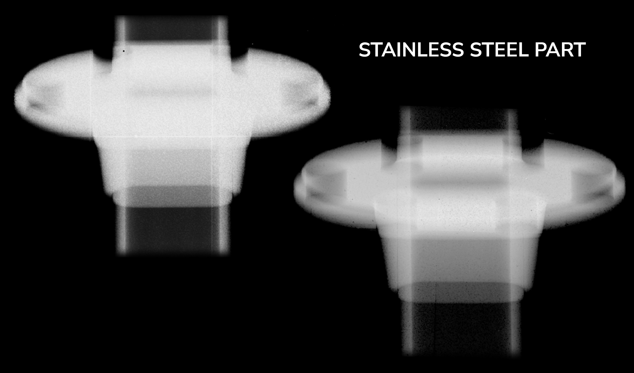
The images compare the same stainless steel component acquired with two different energy thresholds. On the left, the lower threshold allows more scattered radiation to reach the detector, reducing image contrast. On the right, a higher threshold suppresses scattered photons, enhancing contrast and making internal structures easier to distinguish.
High-resolution 2D scan
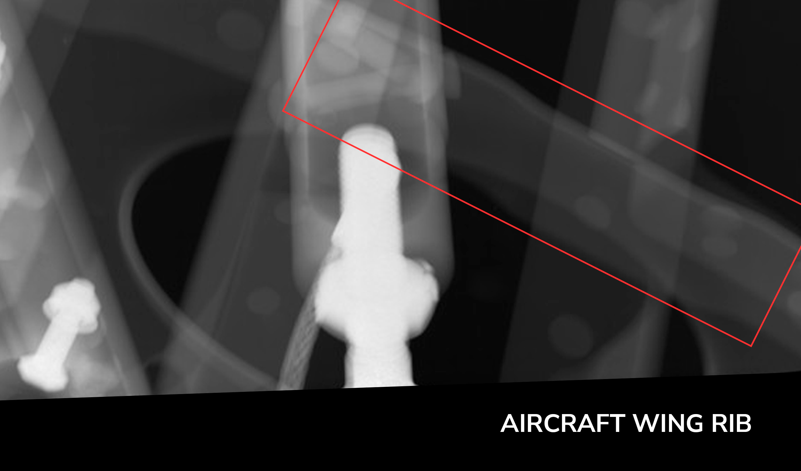
Sometimes you don't need a complete CT scan—you only need accurate information from the region that matters. The image shows a high-resolution scan focused on a wing rib, where the robotic system adapts the inspection geometry to the selected region, revealing internal structural details while avoiding unnecessary scanning of the surrounding aircraft structure.

Backscattering
The imaging detector detects in this case radiation scattered inside the sample. Backscattering requires only a single-side access to inspected objects and therefore could be used in situations where regular X-ray transmission is not applicable due to none or limited access from both sample sides. This approach also allows 3D data acquisition with results that are in their character very close to Computed Tomography.
Best for:

X-ray Diffraction (XRD)
X-Ray diffraction (XRD) provides rich information on atomic arrangement. It can e.g. reveal phase transitions and other heat effects during welding of steel, as well as plastic deformation and residual stress in most materials. Combined with our scanning system, it is a breakthrough in early screening for defects - including fatigue hotspots which didn't develop into a fracture yet.
Best for:
Gallery of scans from X-ray Diffraction (XRD):
XRD scan of Electronics
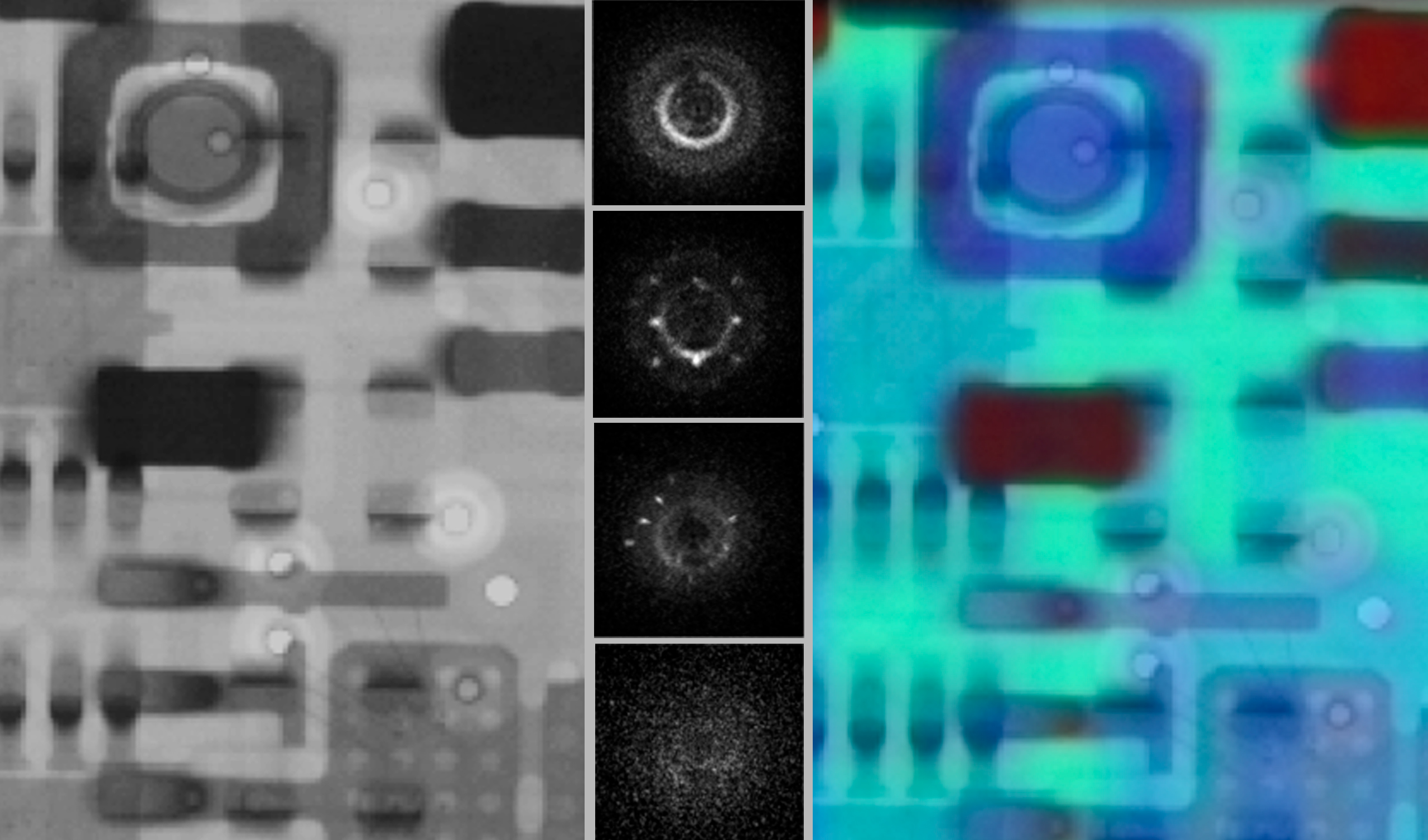
The image shows a 2D XRD scan of an electronic assembly, where diffraction information is collected across the entire scanned area. Using the full diffraction spectrum at every measurement point enables rapid mapping of crystalline phases and material variations, making high-resolution 2D XRD inspection practical for complex electronic components.

Welded sheets of stainless steel
The photograph in the middle marks two measurement locations on a welded component. XRD patterns acquired away from the weld (left) and within the heat-affected zone (right) reveal clear differences in the material's crystalline structure. While conventional X-ray imaging shows the geometry, XRD reveals structural changes caused by the welding process.

Measuring stress in AL
The figure demonstrates XRD-based stress analysis of an aluminium specimen under load. Tensile and compressive stress regions are identified around the loading point, while the lower visualisation converts the XRD data into a graphical map of the stress distribution, with arrows indicating the direction of tensile and compressive loading.

Ultrasound
Our approach to ultrasonic testing uses laser-generated ultrasound and an optical microphone for fully non-contact inspection without the need for a coupling medium. It provides a complementary inspection capability in internal defect detection. The modules are easily interchangeable and both X-ray and ultrasound are acquired within the same coordinate space. It means that correlations between both methods can be evaluated.
Best for:
Laser Profiler
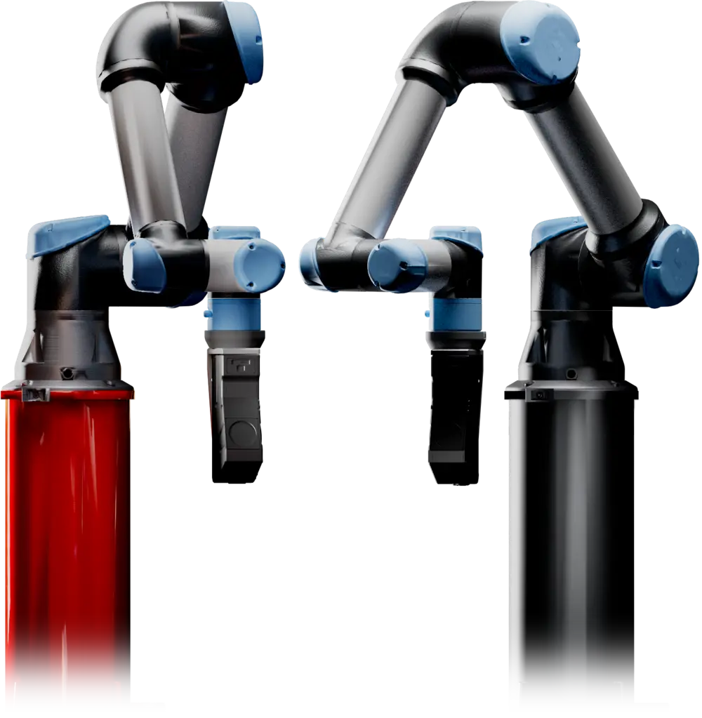
Laser profiling uses laser displacement sensors to capture height data along a line rather than at a single point. This enables 3D characterization of an object surface, including height differences, widths, and angles, using a single sensor.
Best for:
X-Ray Fluorescence (XRF)
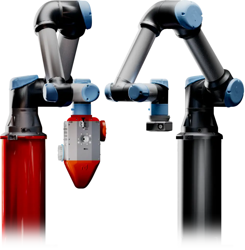
Our scanning system featuring the position- and energy-sensitive TimePIX3 detector allows one to quickly and accurately map surface elemental composition, owing to X-ray fluorescence (XRF) - every element's capability of re-emitting unique X-ray spectrum upon irradiation.
Best for:
Gallery of scans from X-Ray Fluorescence (XRF):
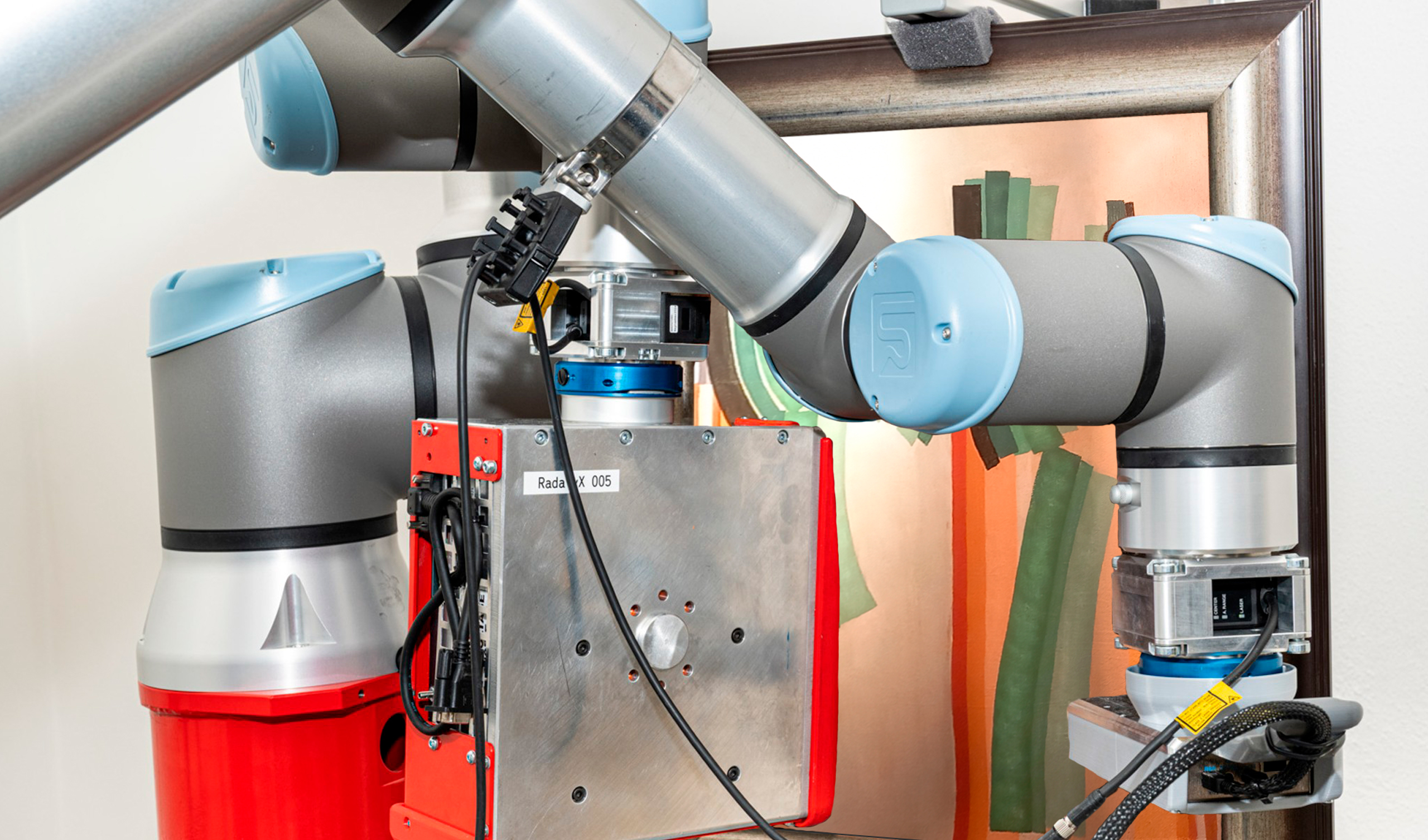
Looking Beneath the Surface
Robots position the X-ray source and the XRF detector easily at a required angle to each other, whith both focused on the same spot on the painting. In this configuration, the entire painting is scanned to acquire XRF data.
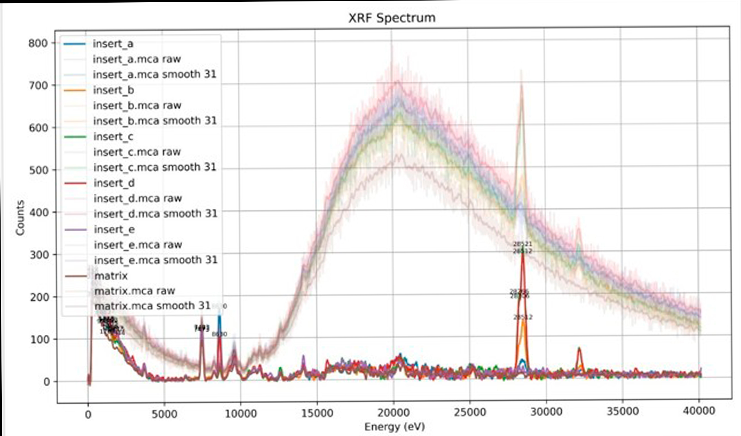
XRF Spectrum
An X-ray fluorescence spectrum is the output of XRF analysis. The spectrum contains peaks at characteristic energies corresponding to specific elements. The spectrum is used to identify which chemical elements are present in the sample.
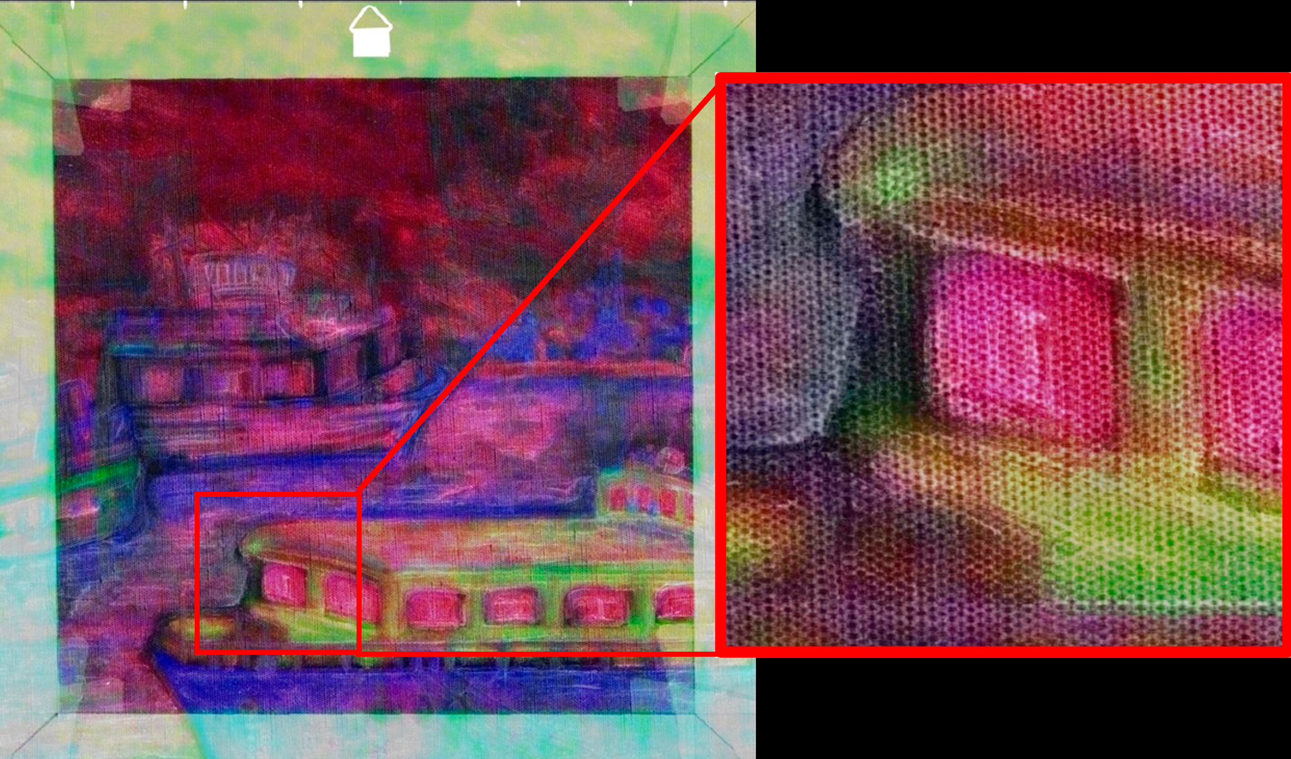
Revealing Hidden Paint Layers
What appears to be a single painting may conceal an entirely different composition beneath the surface. By mapping the distribution of chemical elements, XRF reveals hidden paint layers invisible to the naked eye, helping conservators uncover the artwork's history and verify its origin.
Not sure how to scan your sample?
Send us your sample and we will design solution how to scan it.
Different types of samples may require different strategies of x-ray scans to capture the required information. Let our experts handle it.
#ACCESSORIES
3D Mouse
Software tool for precise real-time universal robot control
Radalytica a.s. has developed a 3D mouse based robot real-time control. Controlling the robot is so precise yet easy to use that it is possible to do even complex operations, like pouring water from a cup.
Real-time imaging with a 3D mouse allows full control over the position and viewing angle of the X-ray image. Simply, once you shift and tilt the 3D Mouse Move, the robot tool will follow the same tilt and shift. The X-ray image of the given area of the sample is displayed in real time on the screen. Simple manual control using live view creates the perfect tool for locating defects in the inspected structure in 3D. Therefore, inspection with robots is faster, less demanding on data processing compared to CT and can be applied to the selected areas of larger object.