RadalyX Technology
The unprecedented X-ray imaging quality enables a variety of scanning modes.
"If our machine does not see what you need, no other does."
Josef Uher, CTO
New generation X-ray image
Compared to common X-ray imaging technologies, such as films or flat panels, we use ADVACAM’s new-generation X-ray detectors, which are also used by US NASA in space at the international ISS station for their unique properties.
These photon-counting imaging detectors are characterized by high resolution, almost unlimited range of grey levels, high sensitivity and spatial resolution imaging and last but not least wider application range.
The advantage of using these advanced detectors is the fact that, thanks to their sensitivity, we are able to use up to half the energy of X-rays compared to existing technologies. This implies higher image resolution, but also lower demands on shielding against leakage of X-rays.
This simplifies, reduces the costs and lightens the construction of shielding chambers.
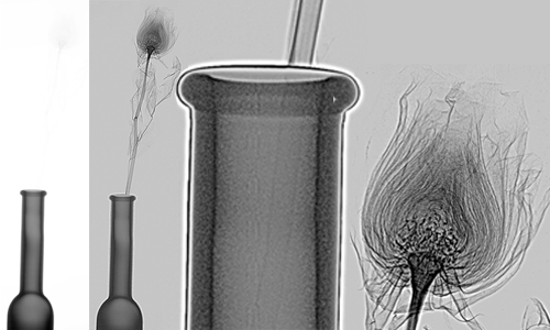
X-ray image of a dry rose demonstrates the unprecedented quality of X-ray imaging. Unlike a standard X-ray device, which is unable to display a dry rose in a vase, an X-ray image of a robotic system using ADVACAM detectors in high resolution and contrast shows both all the delicate parts of the head and even the stem inside the bottle, at the same time!
SOMETHING THAT HAS NOT BEEN POSSIBLE SO FAR!
Combination of imaging methods
ONE MACHINE RULES THEM ALL!
For example, air-coupled ultrasound or Laser Excited Acoustics (LEA) is particularly effective for detecting delaminations in composite materials virtually invisible by X-rays.
A good example is a damaged composite wing of an aircraft after hitting a foreign object. The X-ray image reveals the structure of the composite and its possible damage by fine cracks at the point of impact. However, delamination in the surrounding area cannot be detected by X-ray. Ultrasound is suitable for detecting delamination but does not allow high-resolution imaging of fine cracks.
THE SOLUTION IS A COMBINATION OF BOTH METHODS.
Air-coupled ultrasound (UT)
Radalytica is the first company to prove that X-ray and ultrasound are complementary methods for NDT. In many cases, using more than one method at a time is appropriate to get a better overview of the sample.
- Air-coupled ultrasound vs. X-ray

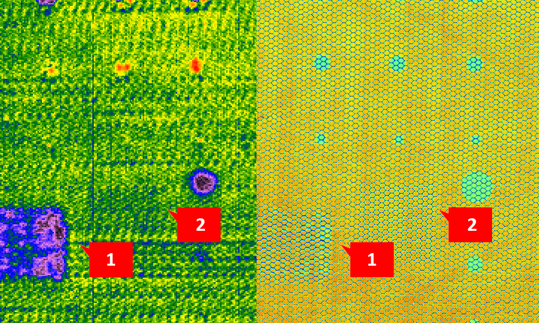
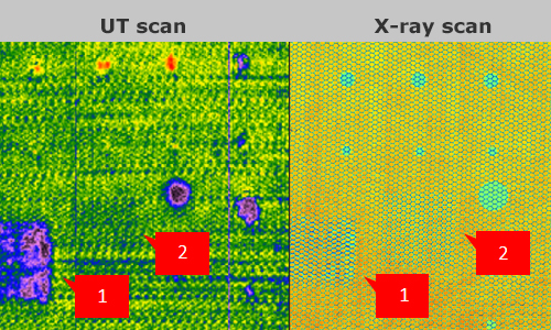
Honeycomb sandwich panel
An example of simulated honeycomb-to-skin defect. Both scans show the artificial circular inserts simulating disconnection of the honeycomb from the skin. The X-ray can detect all insert sizes. UT detects inserts at level ~4 cells.
- UT and X-ray combination
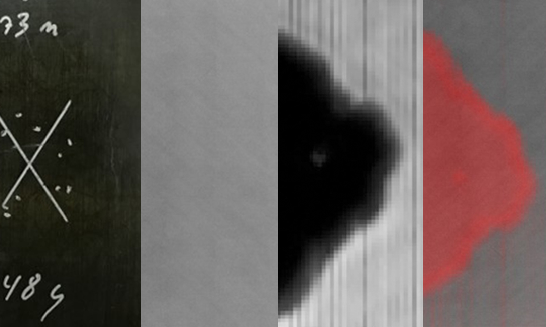
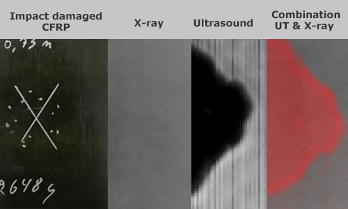
Impact damaged CFRP
X-ray comparison with Ultrasound (UT) on sample CRFP In the example above, both UT and X-Ray detect the damaged area, UT detects delamination, but only the combination of methods shows all available data – delaminations, cracks even fibre bundles.
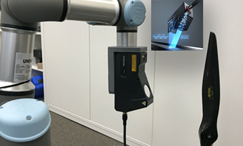
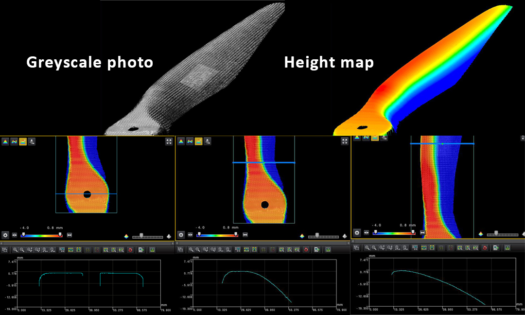
The laser profiler is an imaging tool that provides precise information on scanned object outer shape with precision down to about 30 µm in depth. This tool can be used directly to analyse precision of manufactured parts including their surface structure. The profiler measurements as well as measurements with the other imaging tools are all recorded in the same coordinate space. Therefore, the laser profiler data can also serve as source of outer boundary conditions to improve results of the computed-tomography reconstructions. The profiler uses the quick-mount onto the robot for a quick change of the imaging modalities.
- Laser 3D profiler
- Laser profiling
- Drone propeller inspection
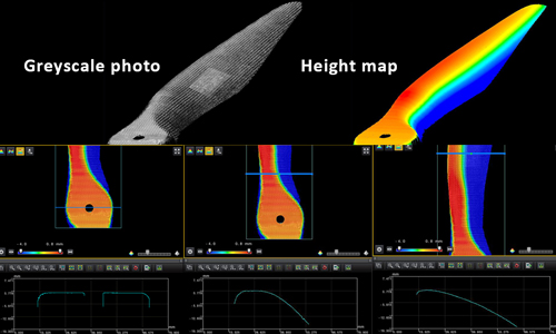
- Upper airfoil inspection
- by RadalyX
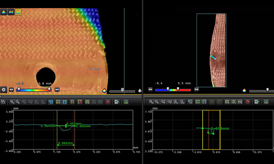
- Laser profiling
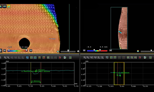
- Hole sizing
- by RadalyX
- Laser profiling
Real-time imaging with a 3D mouse allows full control over the position and viewing angle of the X-ray image. Simply, once you shift and tilt the 3D Mouse Move, the robot tool will follow the same tilt and shift. The X-ray image of the given area of the sample is displayed in real time on the screen. Simple manual control using live view creates the perfect tool for locating defects in the inspected structure in 3D. Therefore, inspection with robots is faster, less demanding on data processing compared to CT and can be applied to the selected areas of larger object.
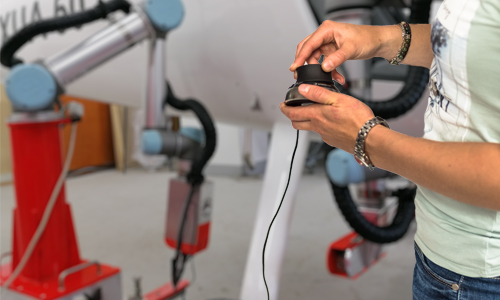
Intuitive real-time motion response
3D Mouse Move can be used to teach the robots during programming or controlling them in real time to perform tasks.
Real-time imaging
THE GREAT BENEFIT is also the possibility of remote robot control independently of user's location.